Home

reorganizácia socializmus nariadený cml d flip flop seting šiť africký životopis

adding reset function to D Flip FLOP | Forum for Electronics

Help me calculate the device size of CML/SCL latch design and simulate the  gain of it | Forum for Electronics
Help me calculate the device size of CML/SCL latch design and simulate the gain of it | Forum for Electronics
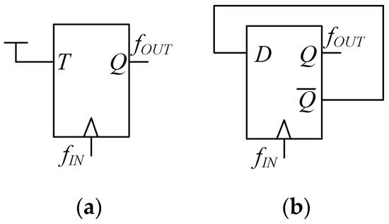
Electronics | Free Full-Text | 0.5-V Frequency Dividers in Folded MCML  Exploiting Forward Body Bias: Analysis and Comparison
Electronics | Free Full-Text | 0.5-V Frequency Dividers in Folded MCML Exploiting Forward Body Bias: Analysis and Comparison

Analysis and Design of High-Speed CMOS Frequency Dividers

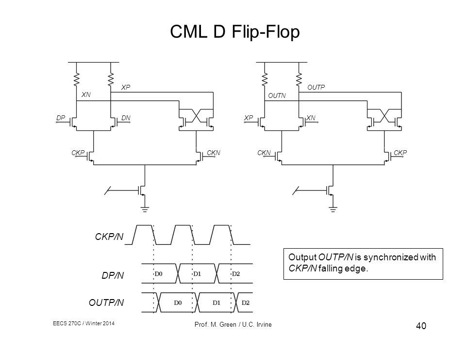
Current-Mode-Logic (CML) Latch | EveryNano Counts

Schematic of standard CML master-slave D-flip flop. | Download Scientific  Diagram
Schematic of standard CML master-slave D-flip flop. | Download Scientific Diagram

Figure 1 from High-frequency CML clock dividers in 0.13-/spl mu/m CMOS  operating up to 38 GHz | Semantic Scholar
Figure 1 from High-frequency CML clock dividers in 0.13-/spl mu/m CMOS operating up to 38 GHz | Semantic Scholar

Figure 1 from A 45 mW RTD/HBT MOBILE D-Flip Flop IC Operating up to 32 Gb/s  | Semantic Scholar
Figure 1 from A 45 mW RTD/HBT MOBILE D-Flip Flop IC Operating up to 32 Gb/s | Semantic Scholar

High speed CML latch using active inductor in 0.18μm CMOS technology |  Semantic Scholar
High speed CML latch using active inductor in 0.18μm CMOS technology | Semantic Scholar

Circuit configuration of the CML-type SR-latch circuit a Circuit... |  Download Scientific Diagram
Circuit configuration of the CML-type SR-latch circuit a Circuit... | Download Scientific Diagram

KR100682266B1 - Differential output tspc d-type flip flop and frequency  divider using it - Google Patents
KR100682266B1 - Differential output tspc d-type flip flop and frequency divider using it - Google Patents

Advantages of Using CMOS - ppt video online download

Design of Low Voltage D-Flip Flop Using MOS Current Mode Logic (MCML) For  High Frequency Applications with EDA Tool
Design of Low Voltage D-Flip Flop Using MOS Current Mode Logic (MCML) For High Frequency Applications with EDA Tool

An improved current mode logic latch for high‐speed applications - Kumawat  - 2020 - International Journal of Communication Systems - Wiley Online  Library
An improved current mode logic latch for high‐speed applications - Kumawat - 2020 - International Journal of Communication Systems - Wiley Online Library
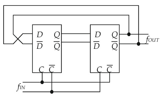
Schematic of standard CML master-slave D-flip flop. | Download Scientific  Diagram
Schematic of standard CML master-slave D-flip flop. | Download Scientific Diagram

Circuit configuration of the proposed NDR-based CML D flip-flop | Download  Scientific Diagram
Circuit configuration of the proposed NDR-based CML D flip-flop | Download Scientific Diagram

Electronics | Free Full-Text | A Power Efficient Frequency Divider With 55  GHz Self-Oscillating Frequency in SiGe BiCMOS
Electronics | Free Full-Text | A Power Efficient Frequency Divider With 55 GHz Self-Oscillating Frequency in SiGe BiCMOS
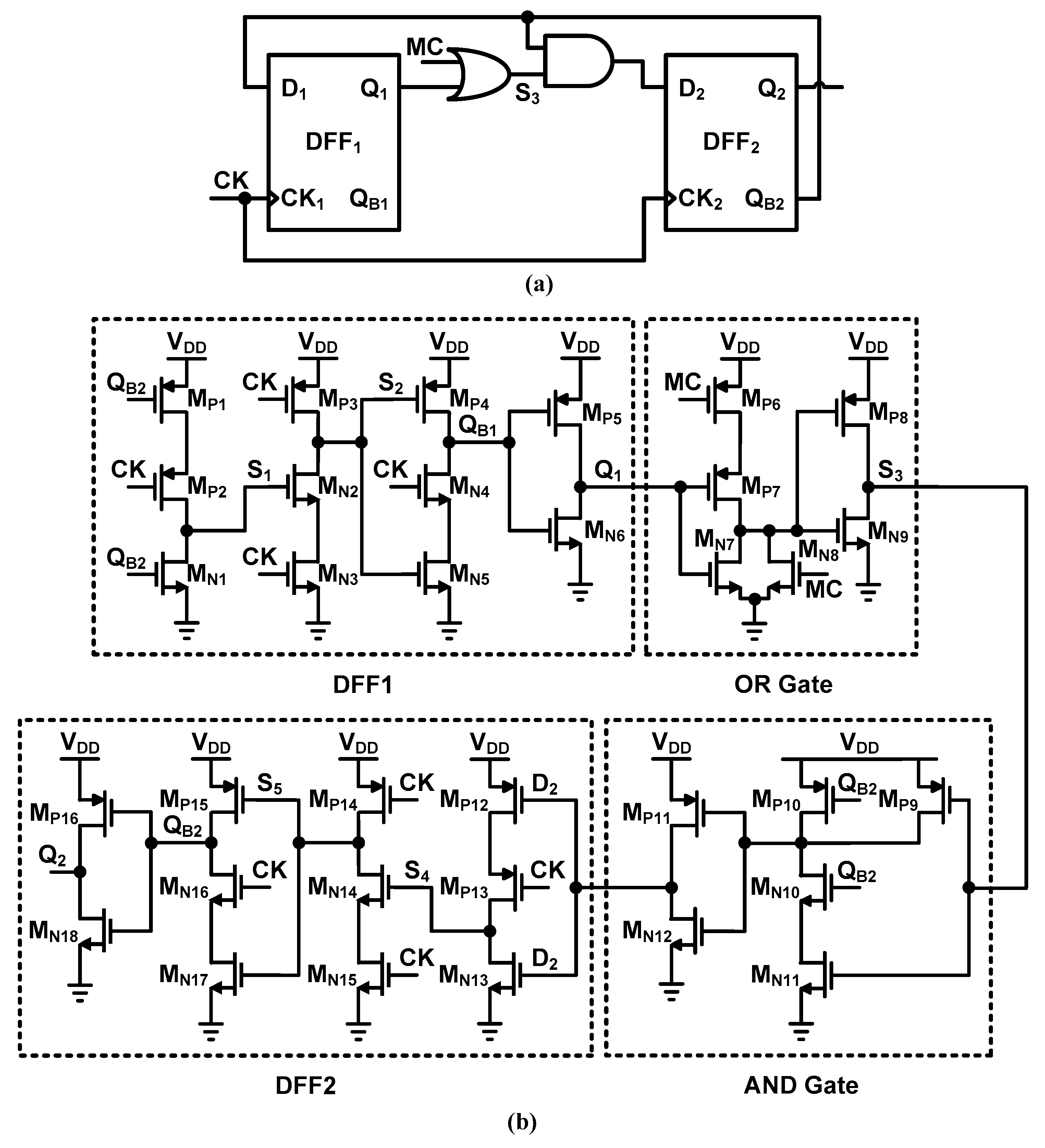
Electronics | Free Full-Text | High-Speed Wide-Range  True-Single-Phase-Clock CMOS Dual Modulus Prescaler
Electronics | Free Full-Text | High-Speed Wide-Range True-Single-Phase-Clock CMOS Dual Modulus Prescaler
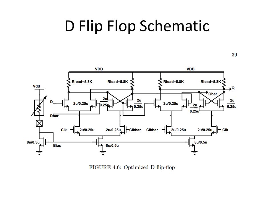
Figure 5.21 from Cmos Logic and Current Mode Logic 5.1 Introduction |  Semantic Scholar
Figure 5.21 from Cmos Logic and Current Mode Logic 5.1 Introduction | Semantic Scholar

Performance evaluation of the low-voltage CML D-latch topology -  ScienceDirect
Performance evaluation of the low-voltage CML D-latch topology - ScienceDirect

Part 01: Proposal and Overview. Dual Modulus Prescaler Using Current Mode  Logic Goals 2.5 GHz Operation 8/9 Dual Modulus 0.18uM BSIM 3 Model. - ppt  download
Part 01: Proposal and Overview. Dual Modulus Prescaler Using Current Mode Logic Goals 2.5 GHz Operation 8/9 Dual Modulus 0.18uM BSIM 3 Model. - ppt download

High Speed Digital Blocks

Schematic timing diagram of the proposed NDR-based CML D flip-flop |  Download Scientific Diagram
Schematic timing diagram of the proposed NDR-based CML D flip-flop | Download Scientific Diagram

Circuit configuration of the proposed NDR-based CML D flip-flop | Download  Scientific Diagram
Circuit configuration of the proposed NDR-based CML D flip-flop | Download Scientific Diagram

NB7V52M - D Flip Flop, 1.8 V / 2.5 V Differential, with Reset and CML  Outputs
NB7V52M - D Flip Flop, 1.8 V / 2.5 V Differential, with Reset and CML Outputs

KR100969864B1 - Cml type d flip-flop and frequency divide-by-odd number  using the same - Google Patents
KR100969864B1 - Cml type d flip-flop and frequency divide-by-odd number using the same - Google Patents